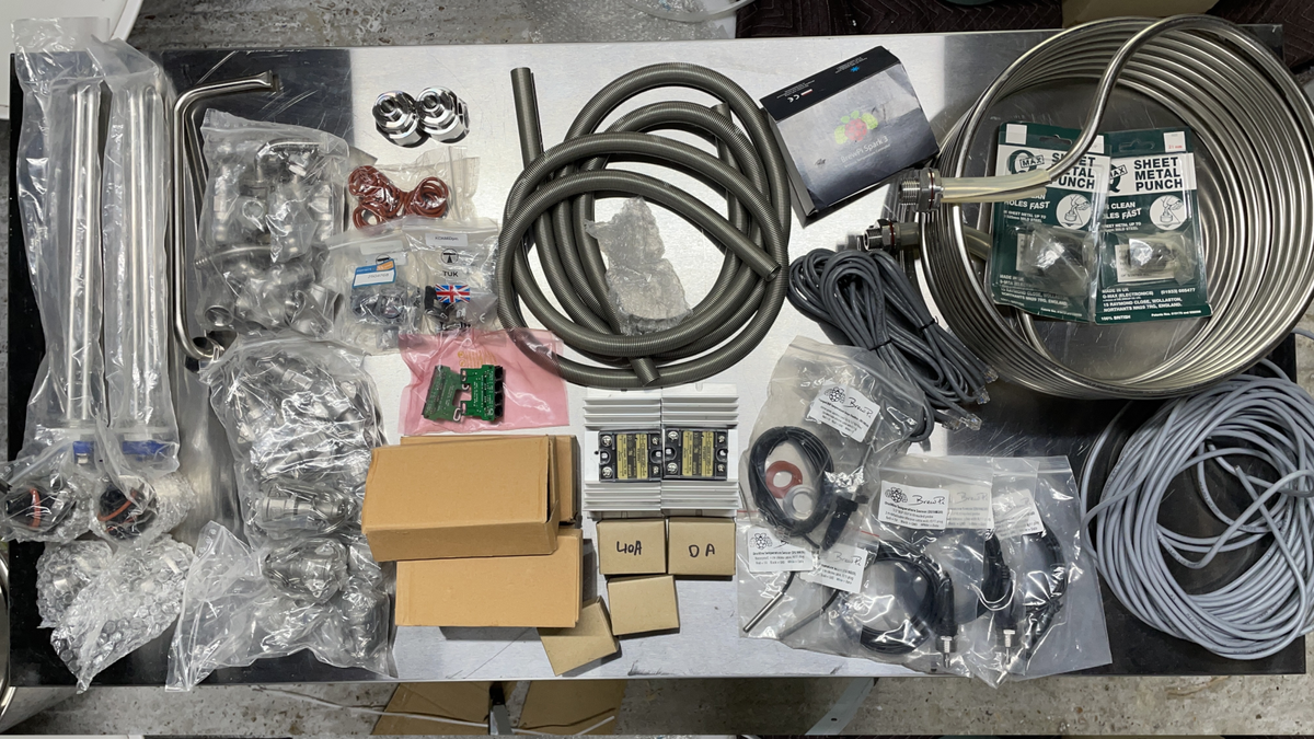
I'd been thinking about this for a while as 4 years had passed since I'd ordered all the parts from BrewPi in the Netherlands and bought three 50l Stainless Pots to convert into my brewery, but I started slowly anyway.
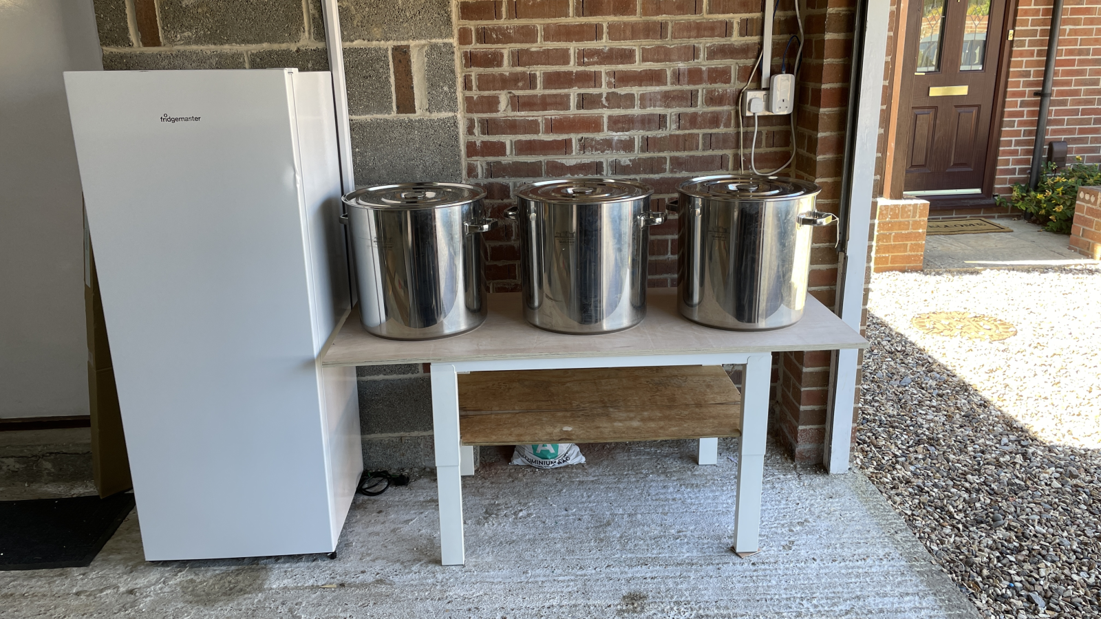
By the time I had finally emptied our container from New Zealand into the garage of our 2nd rented home since arriving back in the UK, I'd also purchased a new-damaged fridge from Appliances Online on eBay to use as a Fermentation chamber controlled by the Spark 3 Brewery Controller I had purchased.
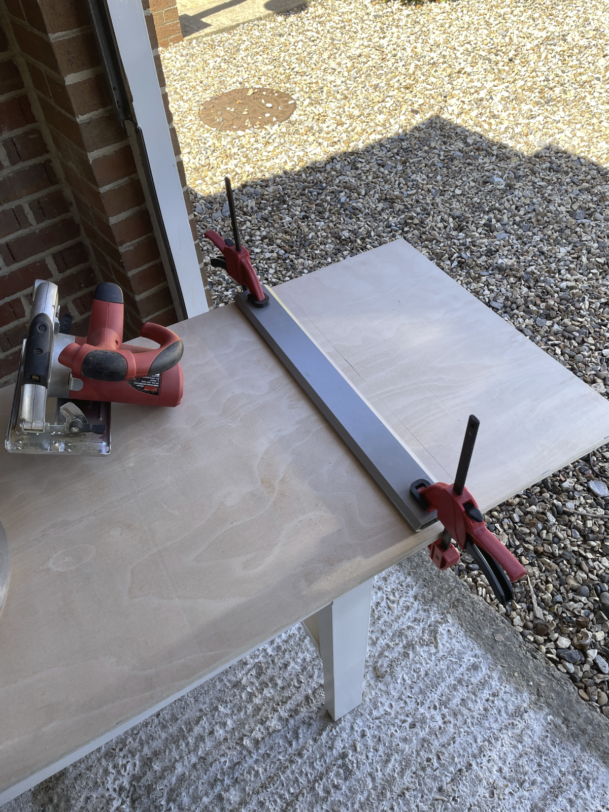
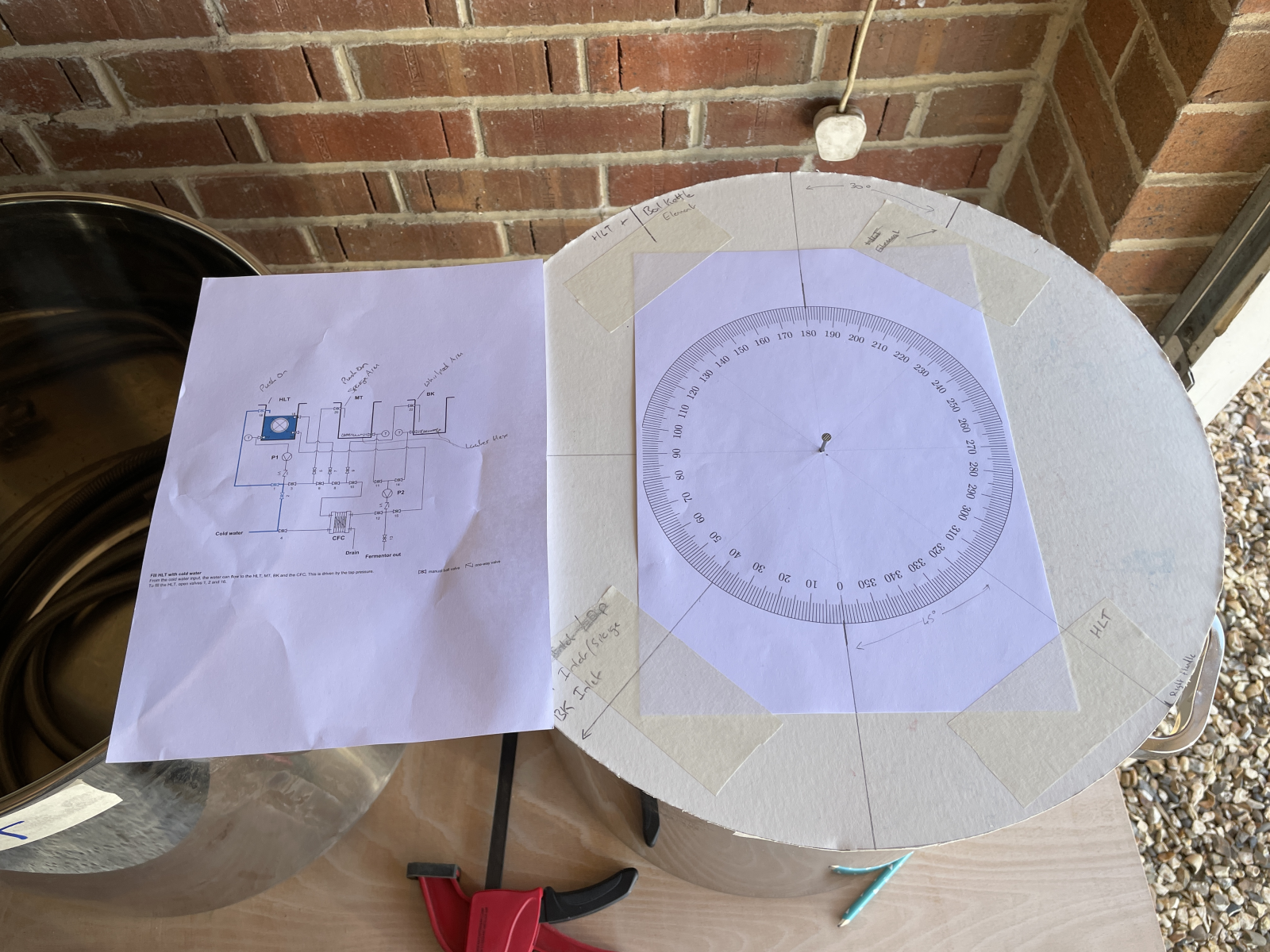
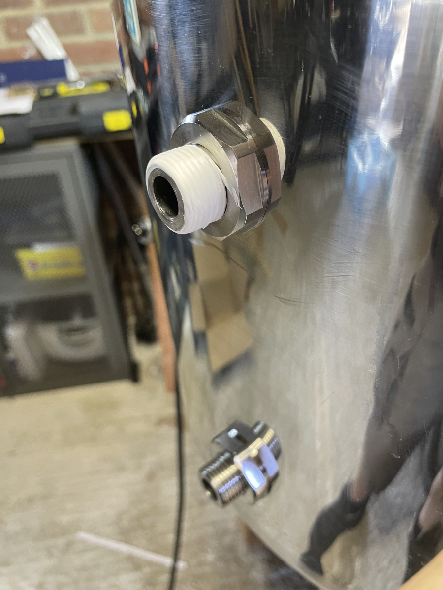
The first step was to mock up the physical layout of the system. This entailed repurposing an old Ikea desk my kids no longer needed with a sheet of 18mm plywood on top, plus working out where I wanted all the holes to be for all the inlets and outlets each vessel has. I'd never liked the idea of hot liquid gushing from an outlet onto my legs so opted to mount all the fittings offset at 45 degrees from the centreline.
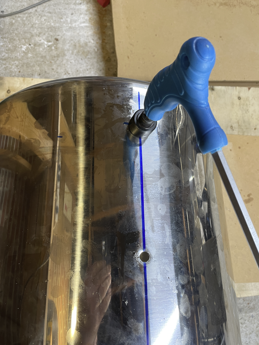
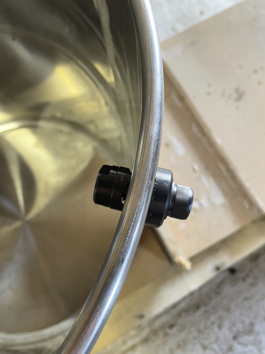
The next step takes some two-handed effort. These vessels may be from China but they're still 1.1 mm thick 304 Stainless Steel and drilling the pilot holes for the Q-Max punches was hard work even with cutting fluid and speed adjustment.
In the end I only made one mistake which continues to haunt me, and a couple I fixed later. In the boil kettle I decided to set the heating element about 4 inches from the bottom. It's no big deal but it does mean that I have to fill the boil kettle with about 10l of wort before I can turn the element on to start the boil.
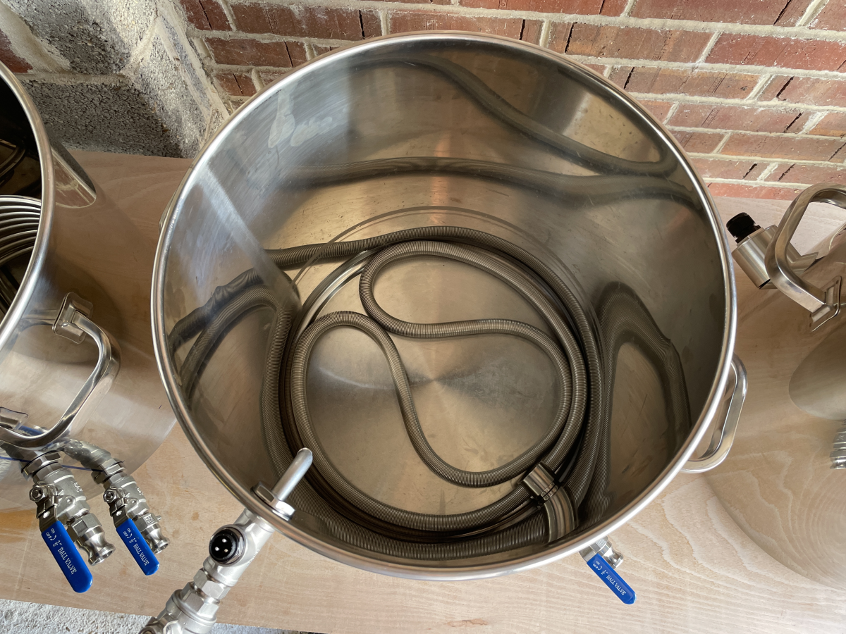
If you're wondering what the stainless steel spring like coil is in the bottom of the Mash Tun, it's a Lauterhexe, a slightly more efficient replacement for a false bottom.
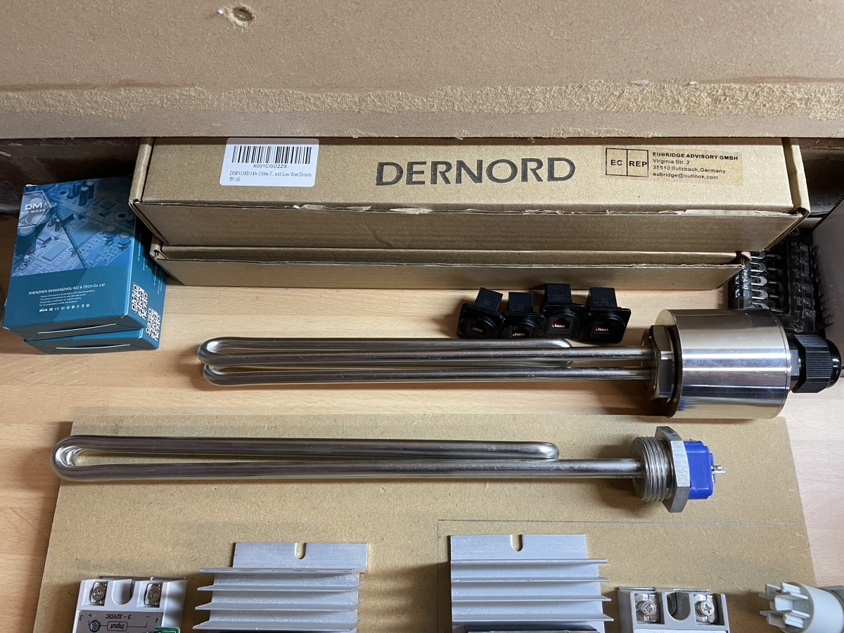
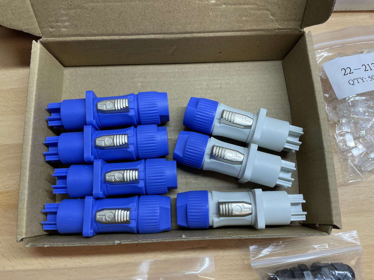
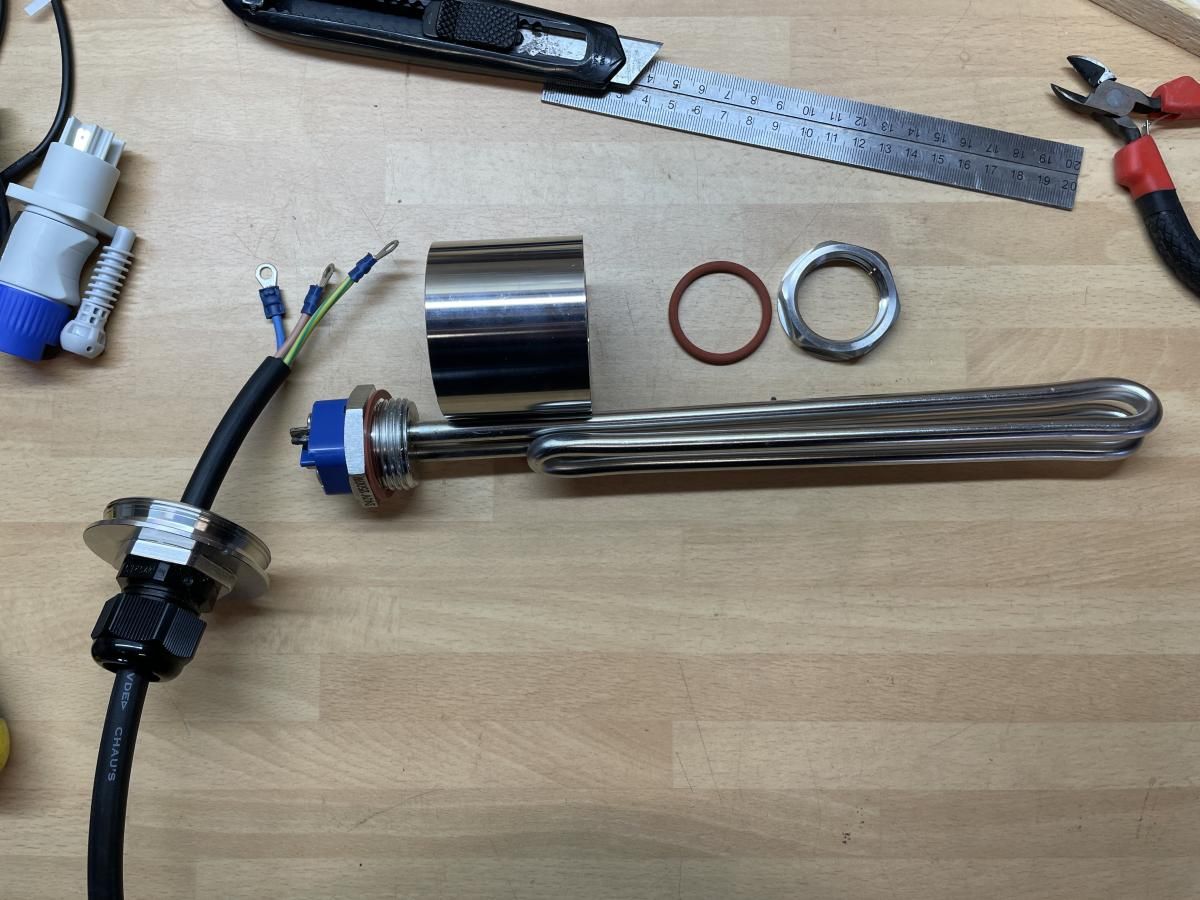
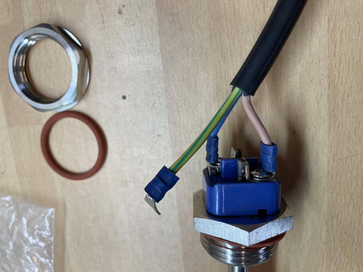
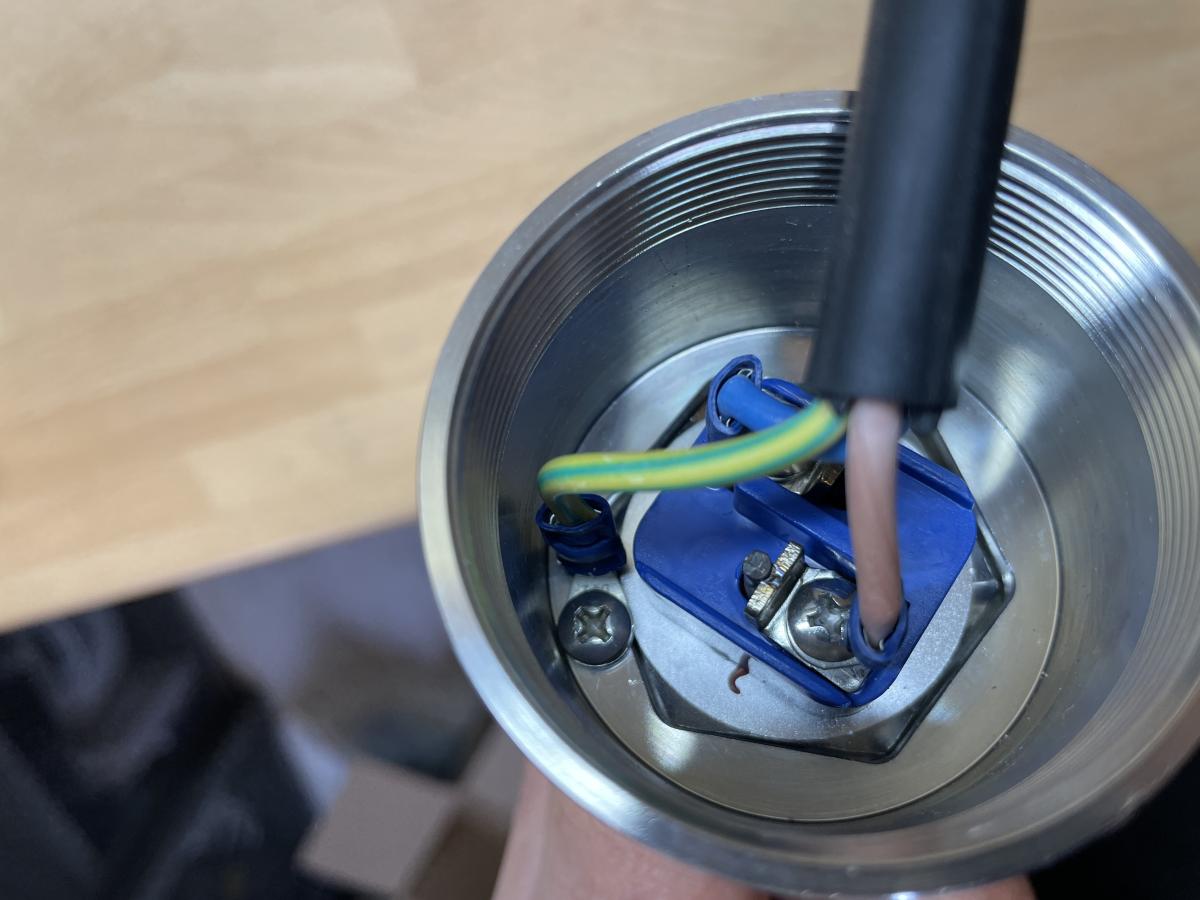
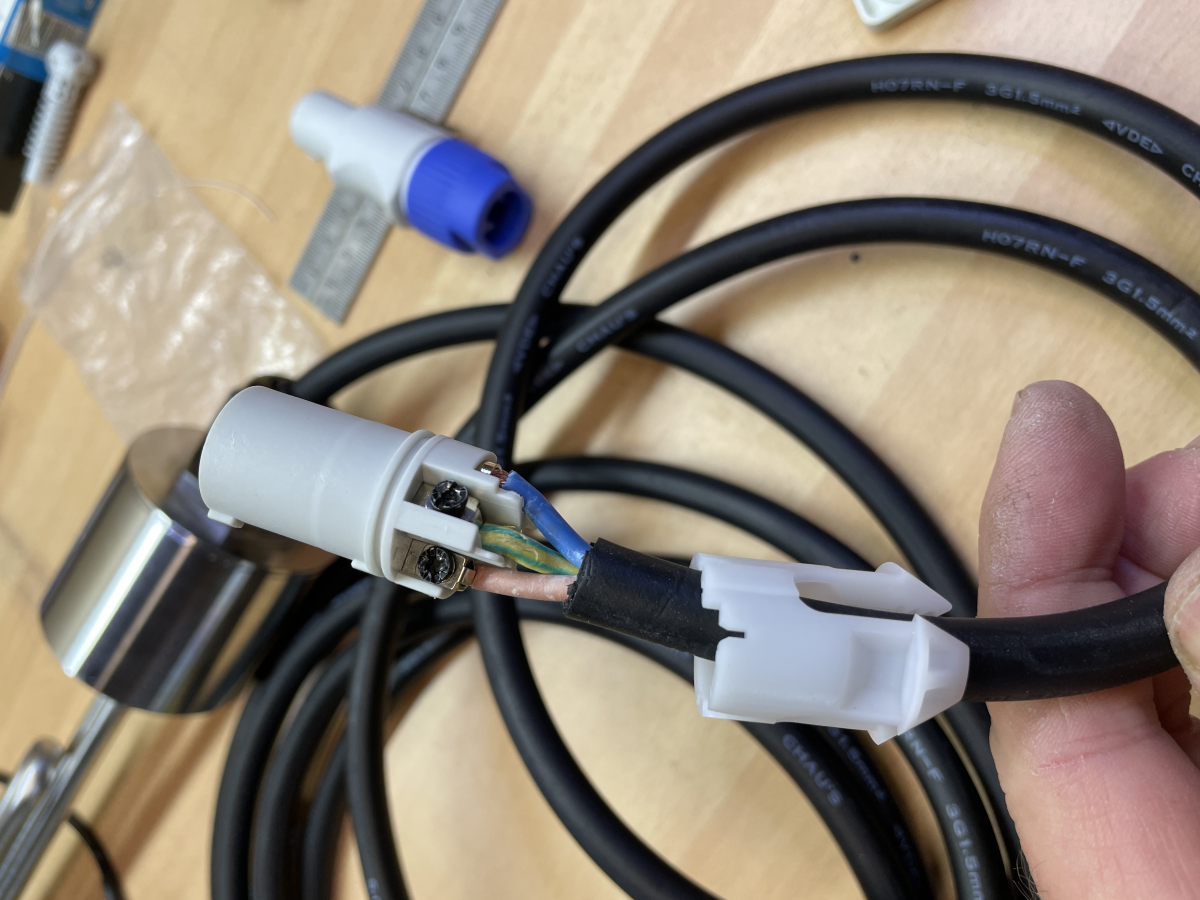
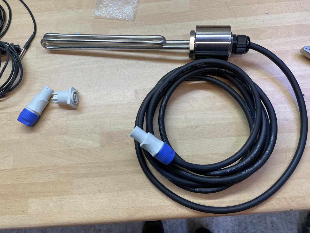
The other small change I made to my original plan was swapping out the 3500w elements for 2400w elements to keep within the 13a limit of the garage and laundry circuits I intended to use to run the system. Here's how the elements are wired up.
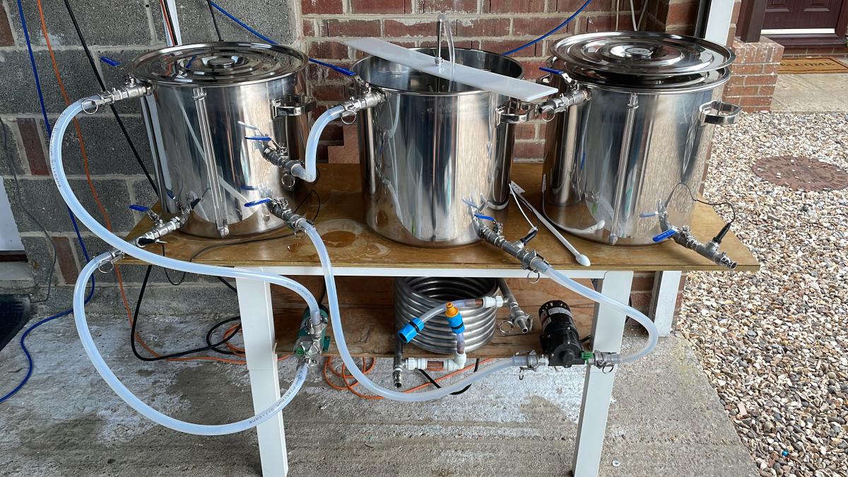
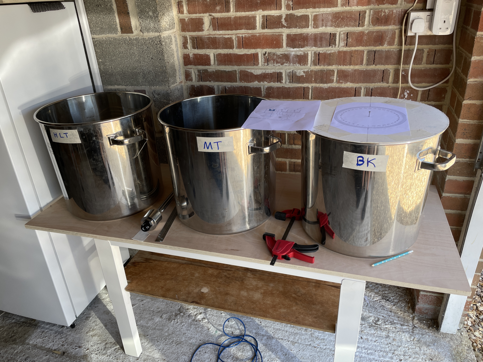
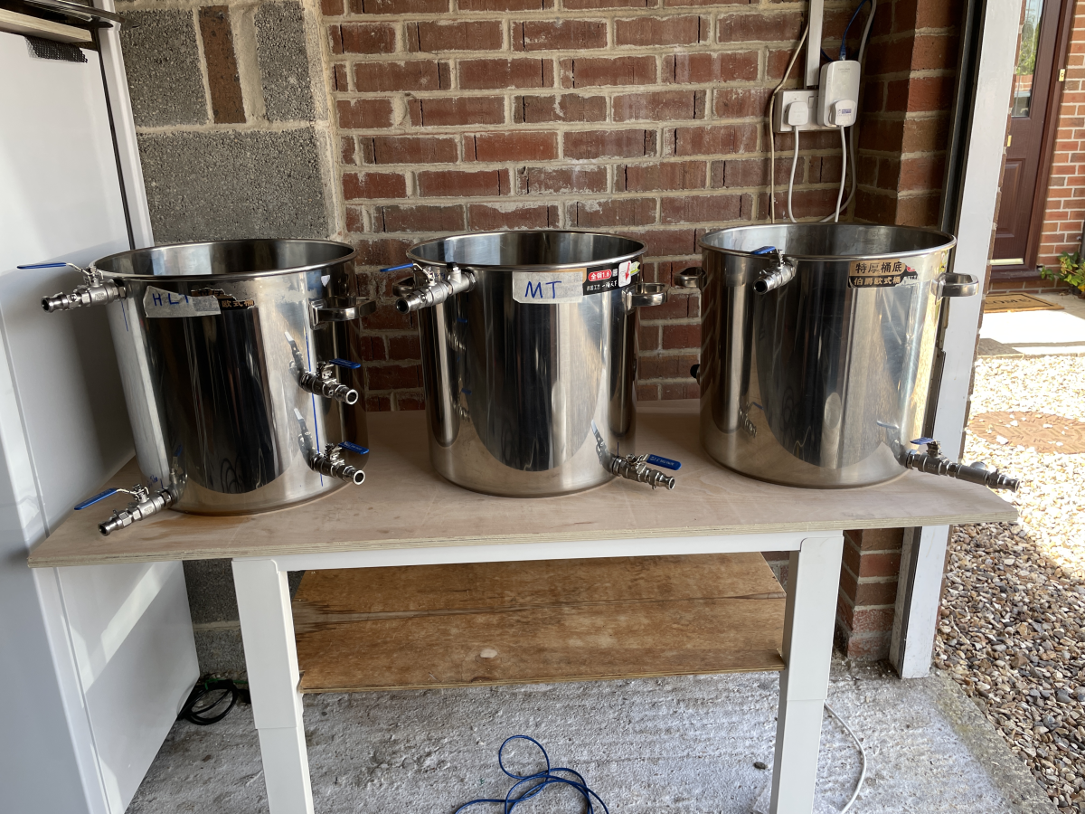
Below is what the system looked like at the end of the build. If you've looked at the BrewPi EHERMs 1.2 design pdf that I based the system on you'll note that I've opted for manual ball valves with manual hose swaps rather than a fully automated system with mechanised ball valves and lots of T-junctions. The other change I made was the placement of the DS18B20 temp sensors, there are 3 in the picture below, all fitted after the ball valves on the primary kettle outlets. If you look closely at the earlier picture above, you can see there was originally one fitted on the upper inlet to the MT which was intended to measure the temp of the wort returning from the HERMs coil. After learning that using an inlet with a hose to return the wort resulted in an undercut grain bed, I decided to use a continuous sparge to gently return the heated wort from the HERMs coil to the MT which bypasses that inlet. The number and placement of the temp sensors has continued to evolve as I've tweaked the system after every brew.
Next, the Fermentation Fridge build, followed by the control boxes build.