If you look at the design of my 3 vessel HERMS system you'll see that it requires one heating element for the Hot Liquor Tank (HLT) and a second for the Boil Kettle (BK). As this is a home system and I'm in the UK, our house is wired for 230V with all the power outlet circuits except for the cooker running on 16 Amp circuits via RCDs on the main distribution board.
The wall outlets are rated at 13A and most plugs are internally fused from 3A up to 13A max to protect the outlet. So given Watts = (V x A) the maximum wattage heating element I can have on a single circuit is ~ 3000 or 3kw.
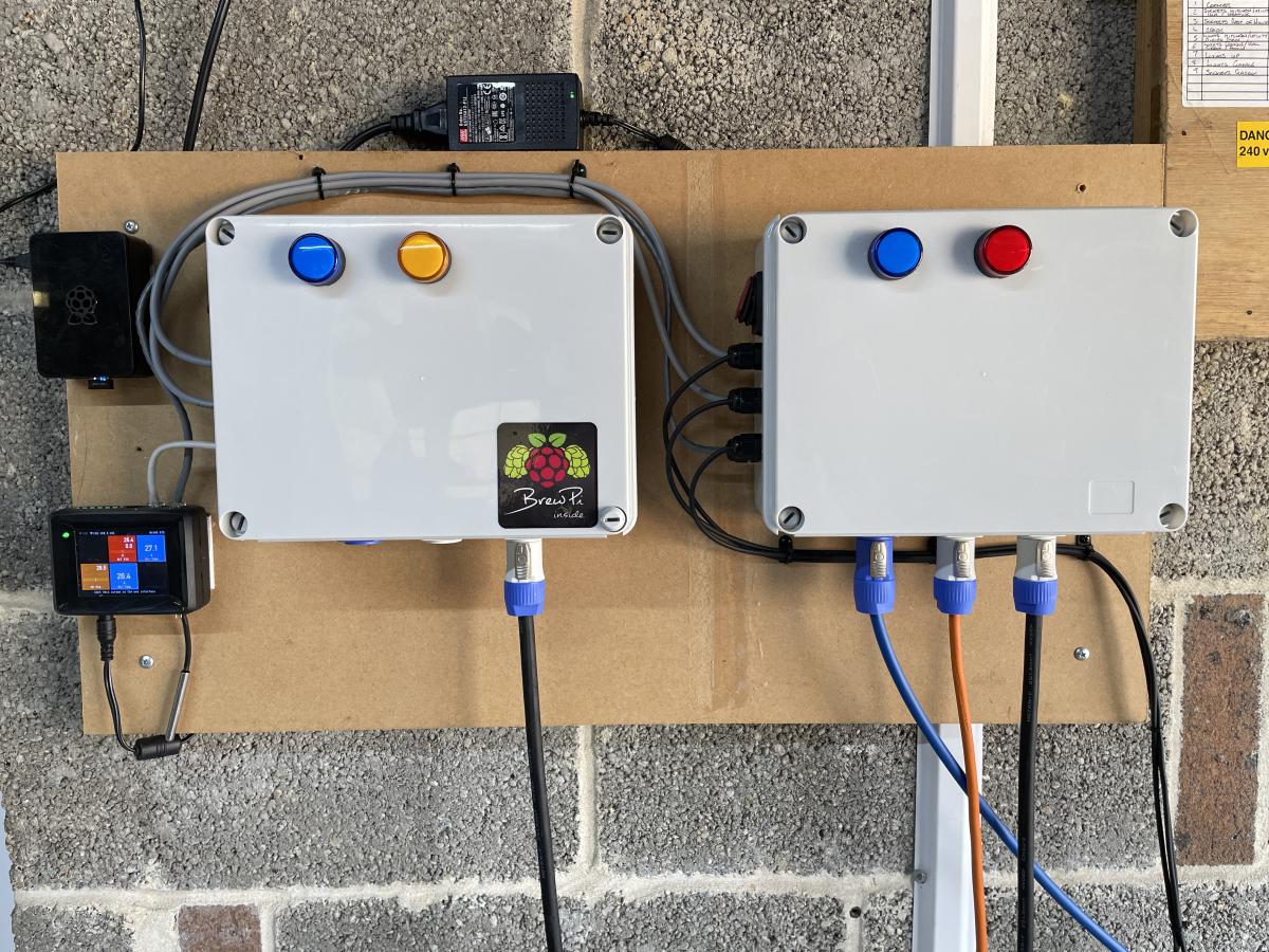
Luckily, the house's distribution board is in the garage, right above the space where I wanted to sit the brewstand, and as it happened there was a wall outlet there, and a second 16a feed that goes through a hole in the wall into our laundry. That hole is big enough to run a another cable so this is how I power the brewery, one 230v x 13a feed from the garage circuit powering the BK element + pump via Cab B and a second 230v x 13a feed from the laundry back through the wall powering the HLT element + pump via Cab A.
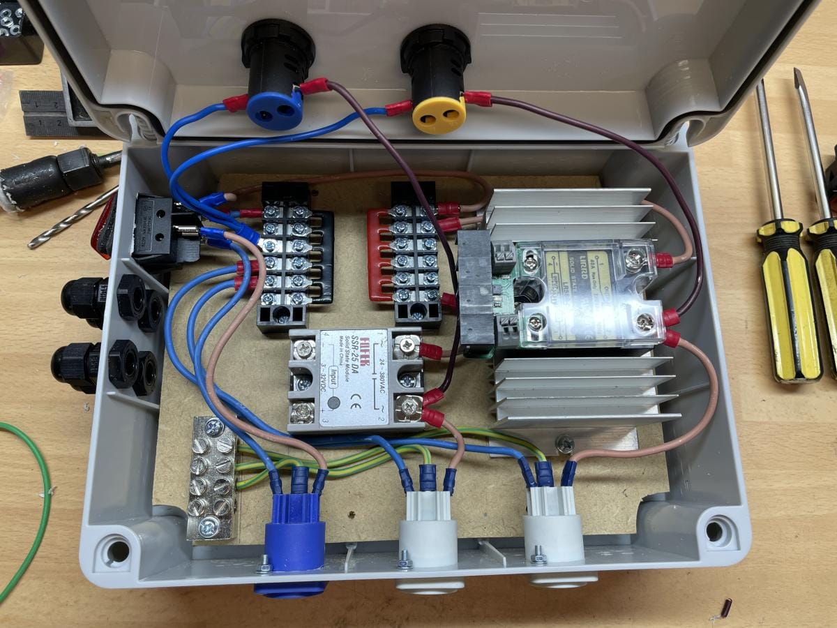
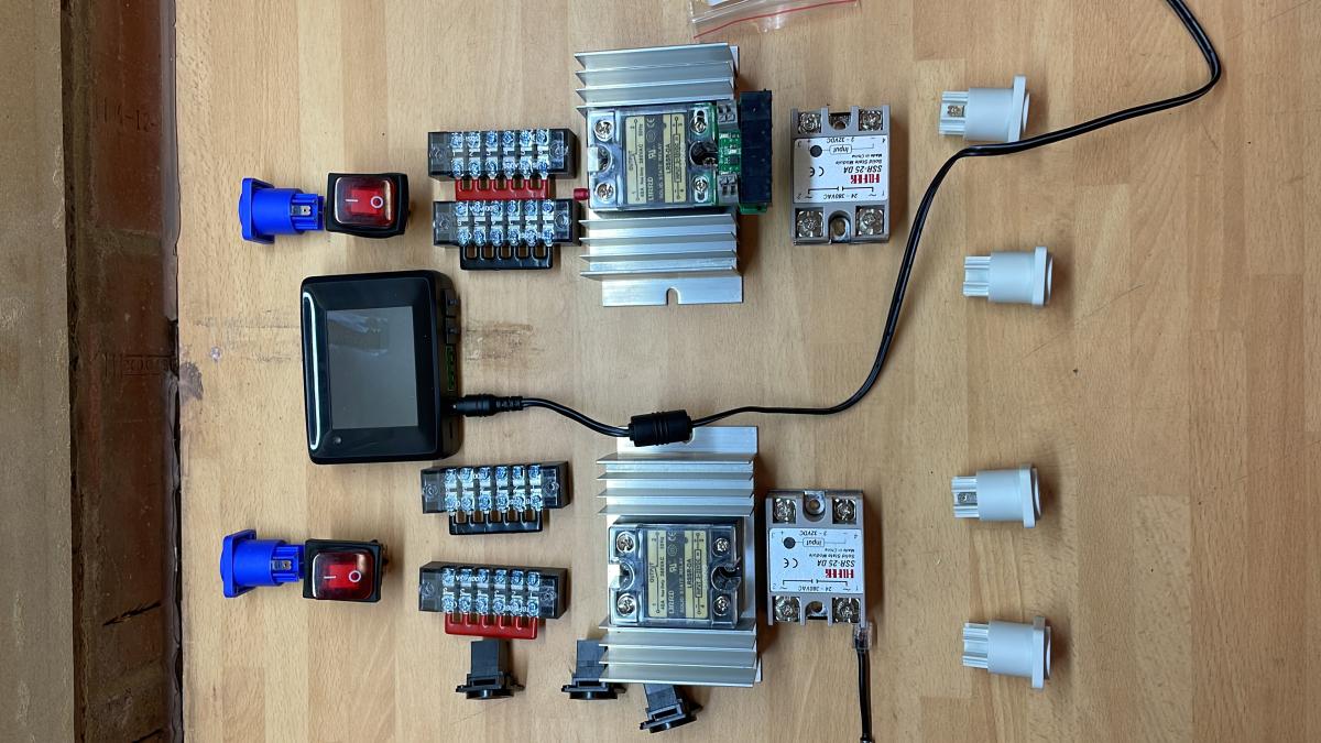
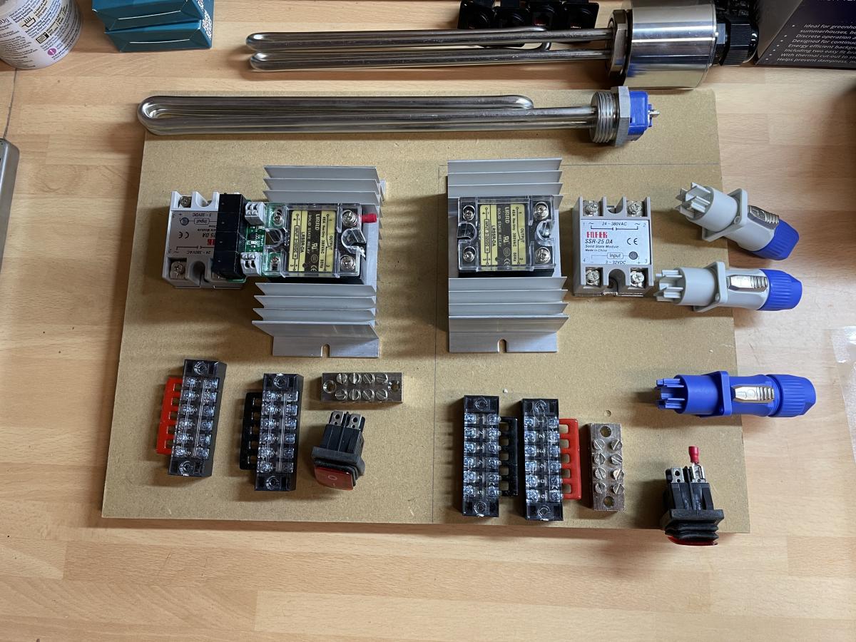
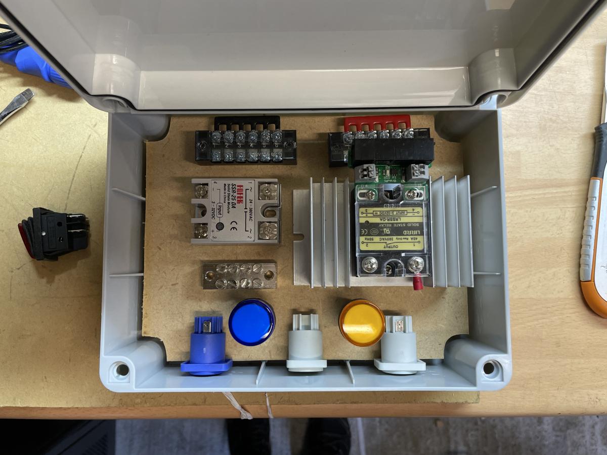
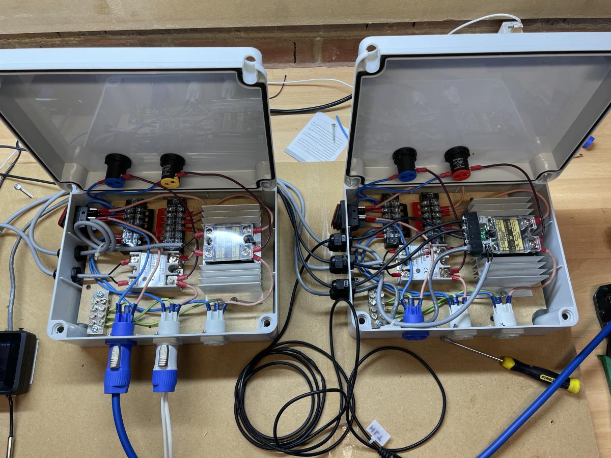
I originally thought about having all the electrics in a single IP66 electrical enclosure (see 1st photo) but quickly resolved that to reduce heat and overall complexity, it would be simpler to build one box for for the HLT and another for the BK and keep each circuit isolated. The smaller junction boxes I used were a lot less expensive too.
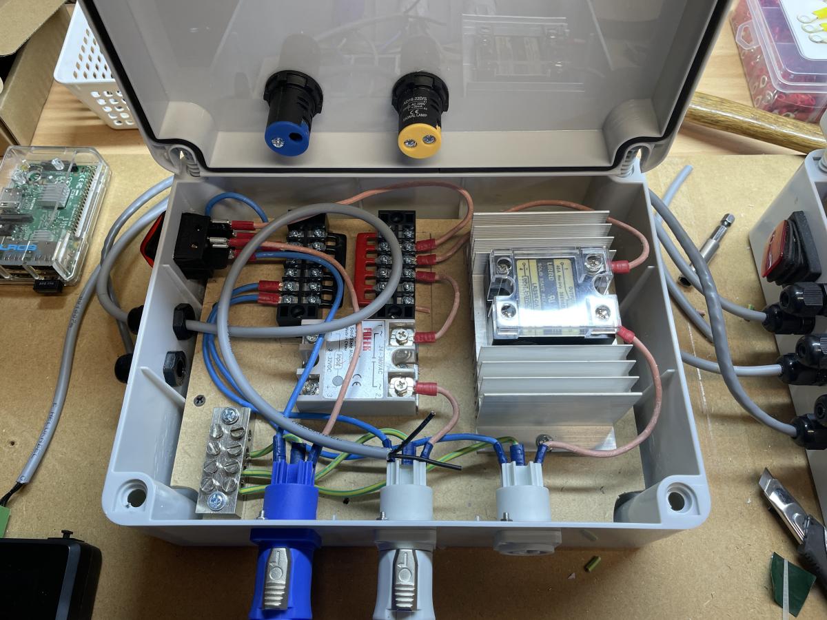
Each box receives a 230v feed via a blue Neutrik PowerCon connector . This is switched through a 16A switch and then distributed via 2 buses to the 2 Solid State Relays in each box. There's also a ground bus. The black SSR sitting within the aluminium heatsink is 40A and switches power to the box's assigned heating element (HLT or BK), while the smaller silver 'Fostek' SSR is only 10A and switches power to a pump. These 230v out feeds are routed via the grey Neutrik PowerCon connectors.
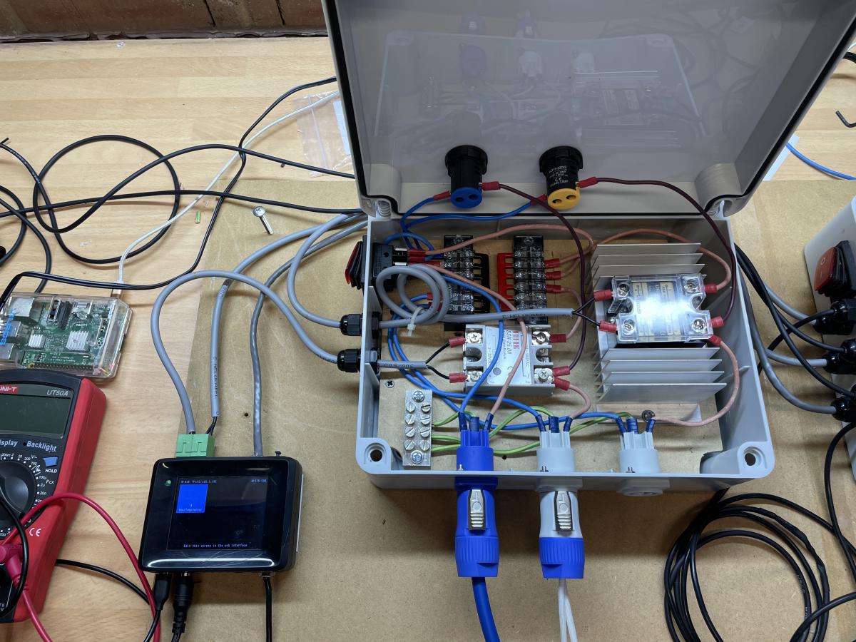
As before with the Fridge, the SSRs are controlled via a 1-Wire SSR Expansion board connected to the BrewPi Spark 3 with an RJ12 cable. There's only one shown in the photos with additional 5v trigger feeds for the pumps coming from the BrewPi Spark's green pin-out connectors however I resolved in the end to keep it simple and consistent and used a 2nd SSR Expansion in the Cab A on the left connected to both of the 10A SSRs to control the pumps.
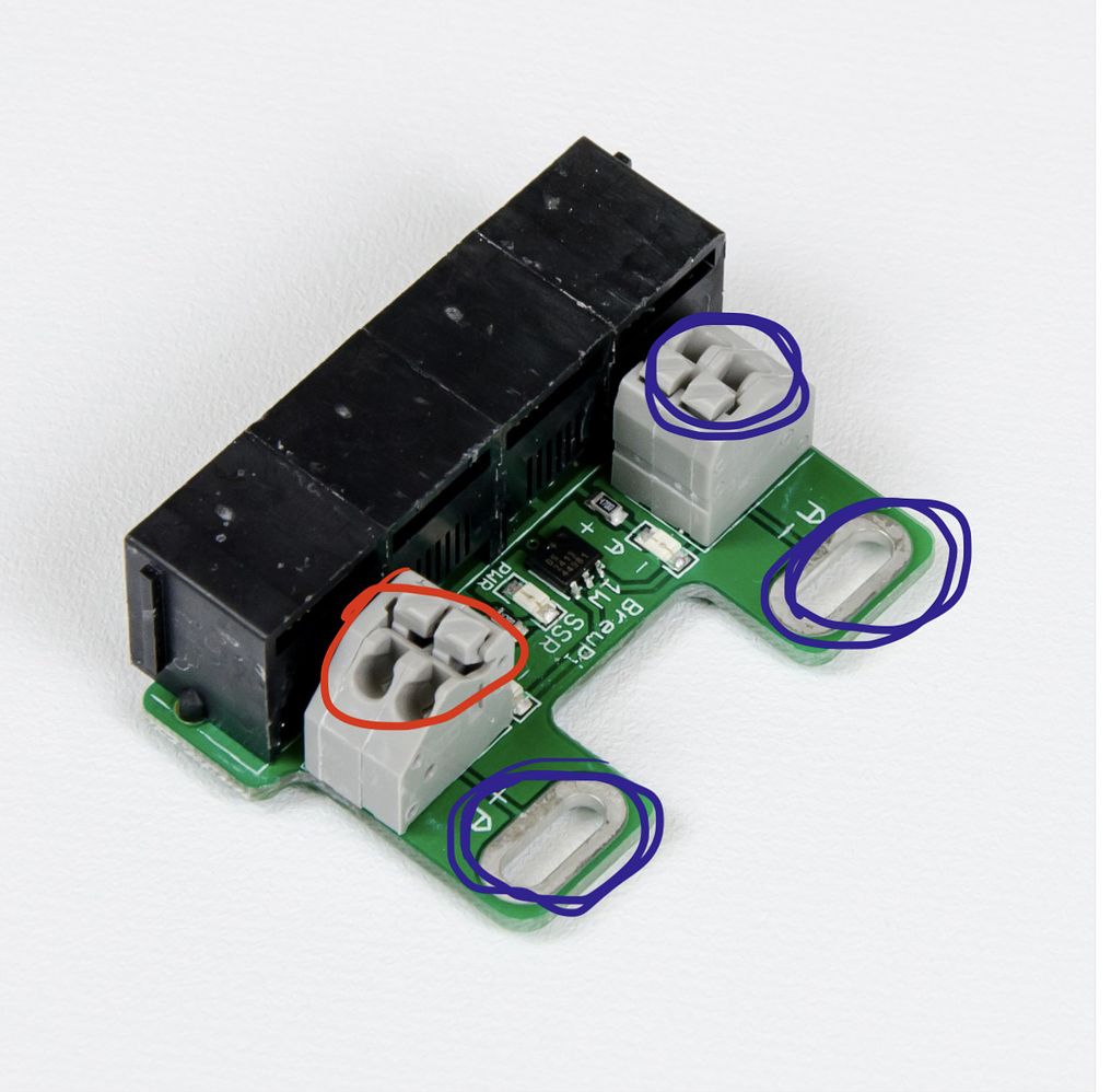
If I were to do this again (and I may rebuild the system one day), I'd aggregate all the temp sensor feeds into a separate box (aka, a switch) below the brewstand's top shelf, and have a single RJ11 cable running back to the Spark 3 and only one RJ11 line running into each controller box to trigger each of the SSR expansion boards. I might also add some forced ventilation, though heat hasn't been an issue so far as the SSR's run pretty cool.
Next; on to Part 4 - Install and setup BrewBlox