Early into my journey I read that controlling fermentation was the secret to making great beer consistently. As building the skills to one day maybe run my own commercial brewery was one of my goals, I knew from the outset that the fermentation processes and equipment were going to be at the centre of my home brewery.
Then I discovered BrewPi in early 2017 which was at version 2 where fermentation control was it's primary focus, with plans to extend that to brewing control with Spark 3.
By the time I ordered all my kit in Dec 2017, Spark 3 was in production and accompanied by a pretty detailed Fridge Hacking Guide that explains exactly how to turn a standard fridge into a very precise temperature controlled fermentation chamber.
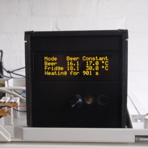
"The BrewPi Spark 3 is a temperature controller that can control your beer or wine fermentation with 0.1°C precision. It sends data to a Raspberry Pi (running BrewBlox) to show a control panel with graphs in your browser. And all our software is open source!"
The BrewPi Spark replaces the controller that sits on the front of an all-in-one system like a GrainFather. A functional layout of a typical system has all the components shown in the image below plus a Raspberry Pi which provides the web based user interface.
- The Spark 3 brewery controller designed by Elco Jacobs of BrewPi in the Netherlands.
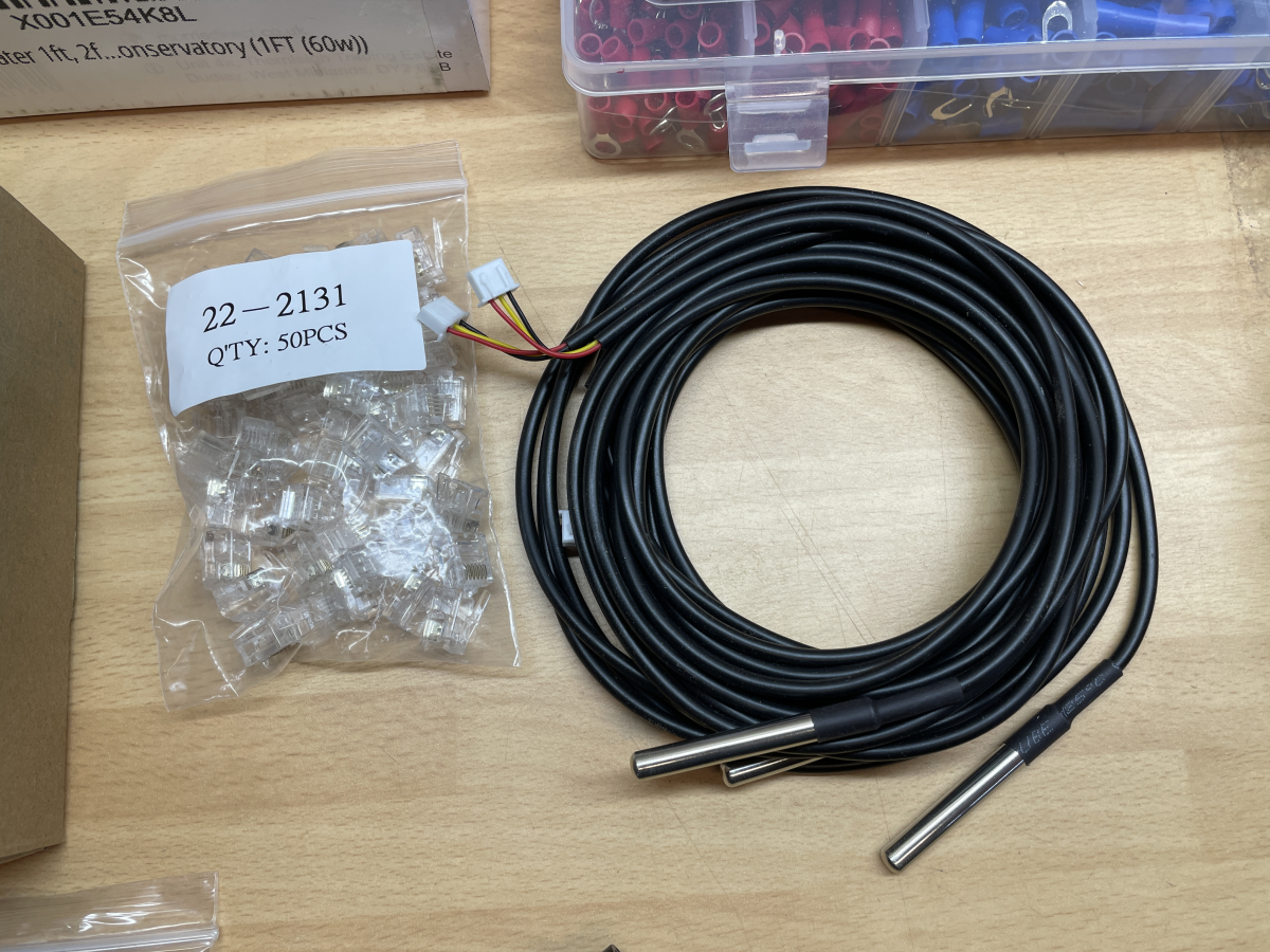
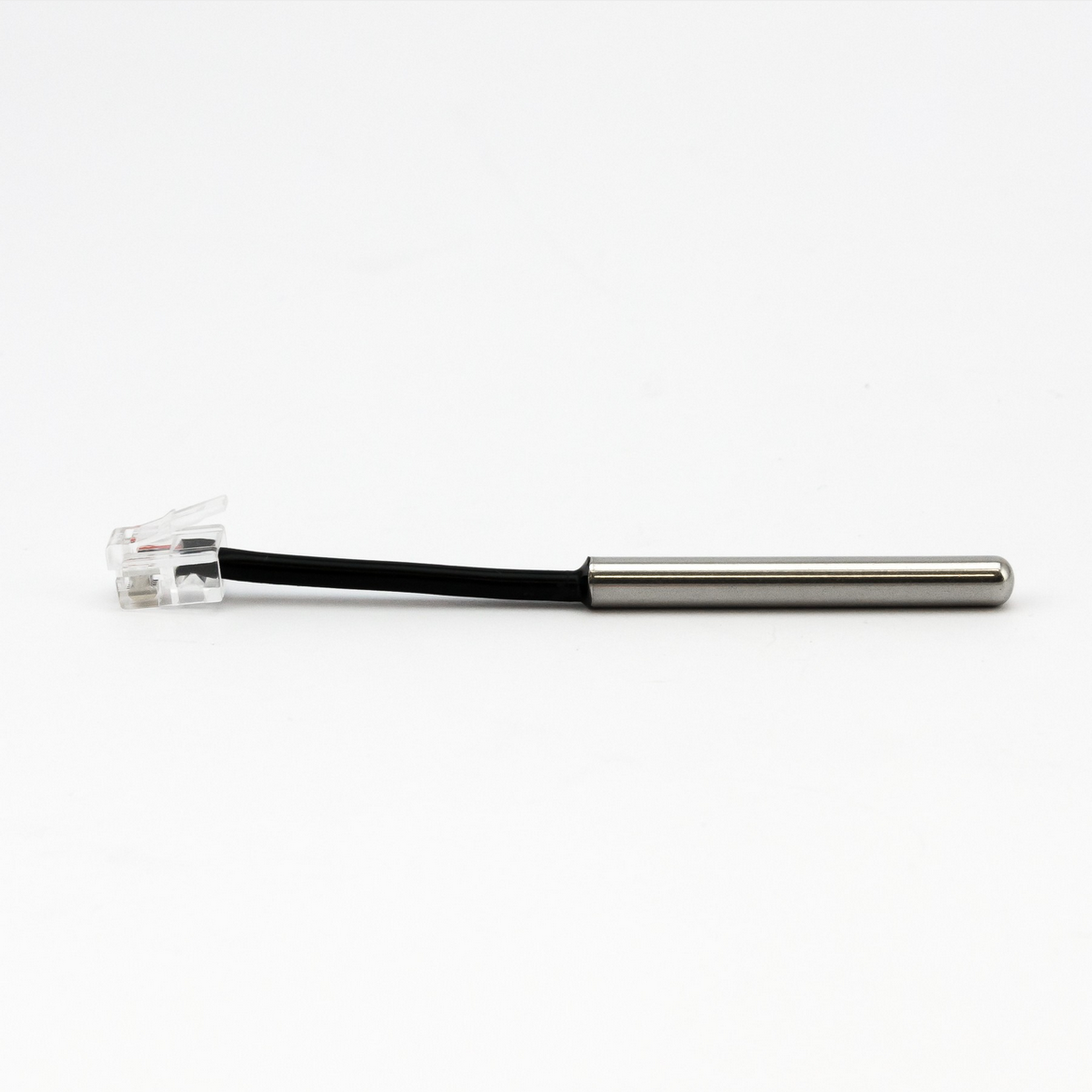
- Different types of DS18B20 digital 12 bit temperature sensors. These have a 0.0625 °C resolution and are more stable than analog LM35 sensors used in other systems. They provide input for the software PIDS which then turn on/off heating and cooling circuits via the Solid State Relays (3). (We'll look at the software later.)
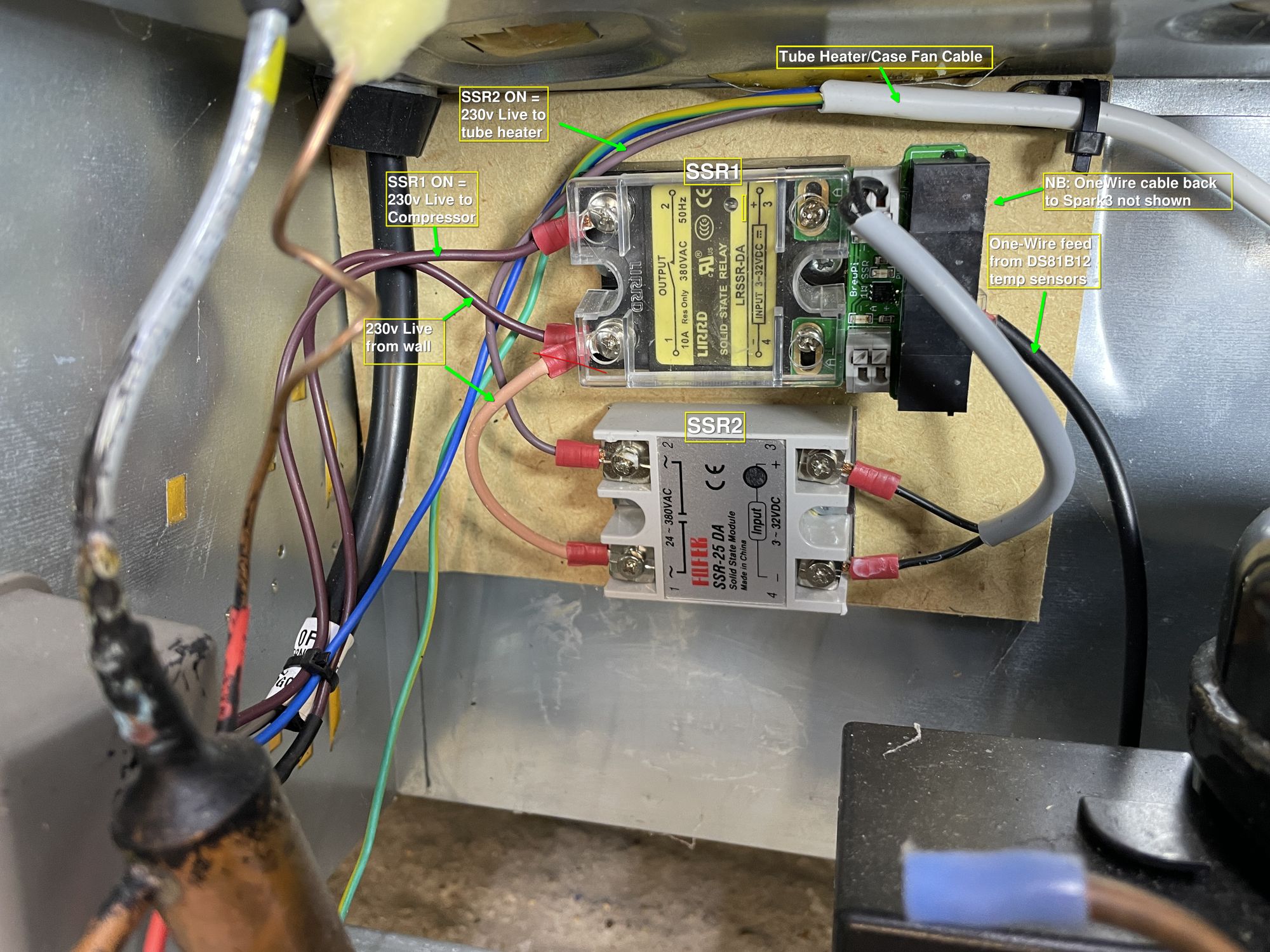
- Solid State Relays - these are essentially switches used to turn anything electrical on/off such as the tube heater and the fridge's cooling circuit in the case of the fermentation chamber, or a pump or a brewing vessel heating element. A 5v input signal on one side closes the switch of the 230v circuit on the other side. NB: the 230v side is not wired up in the photo below. Only the 5v side is shown
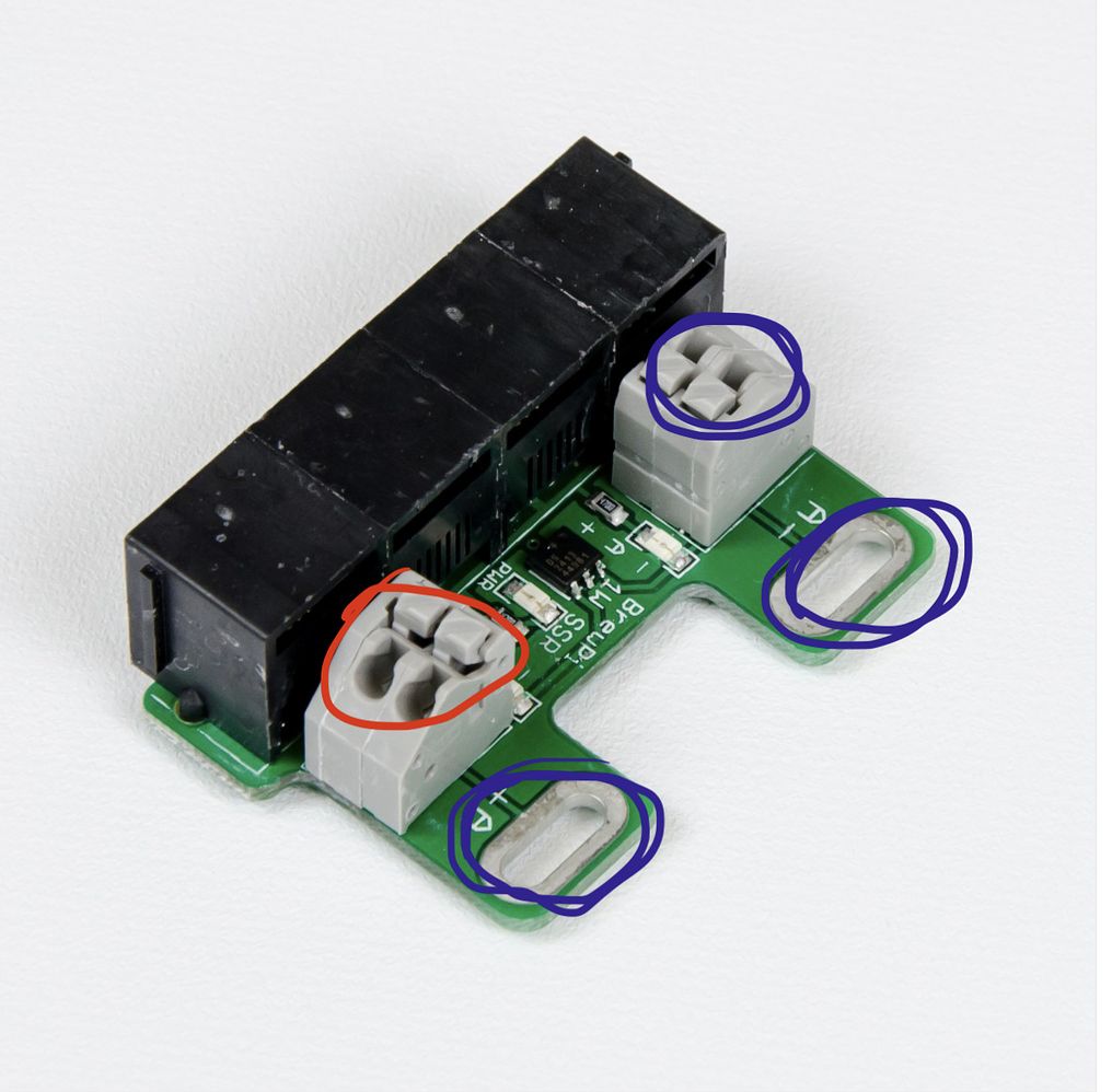
- This is a Solid State Relay expansion board, shown in greater detail below. It can control 2 SSR's, one by being screwed directly across the SSR terminals as shown below, and one via a cable connected to the 2nd terminal block shown on the left below.
- These are direct 5v/12v pinouts (configurable) on the Spark 3 which can be used to send a 5v/12v signal directly to a device, in this case a much larger 3-Phase SSR (bottom left) that would be used to heat a large brewing vessel.
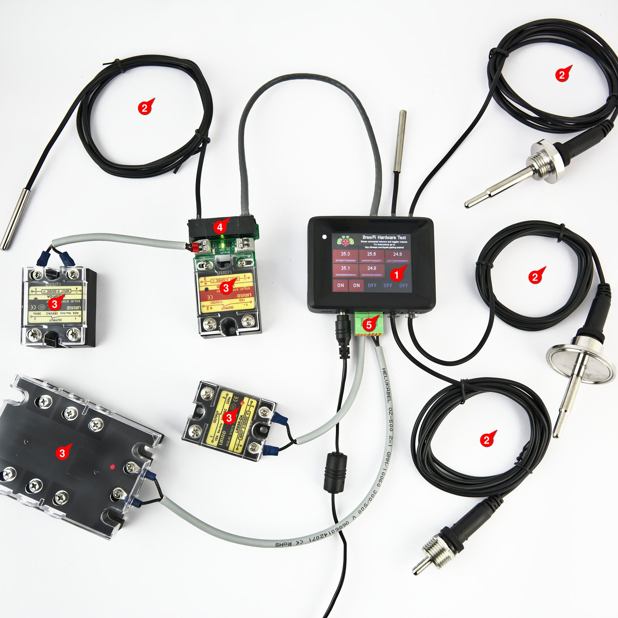
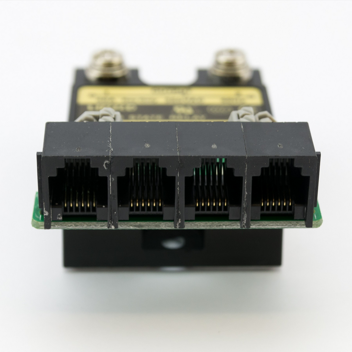
All the components of the system communicate with the Spark 3 via the 1-Wire protocol. This allows the Spark to communicate and manage up to 100 devices via a single RJ11 interface. In practice the Spark 3 has six RJ11 interfaces and each SSR expansion board has 4 as shown below allowing multiple devices to be easily daisy chained together. This will come in handy later.
My Fridge Build
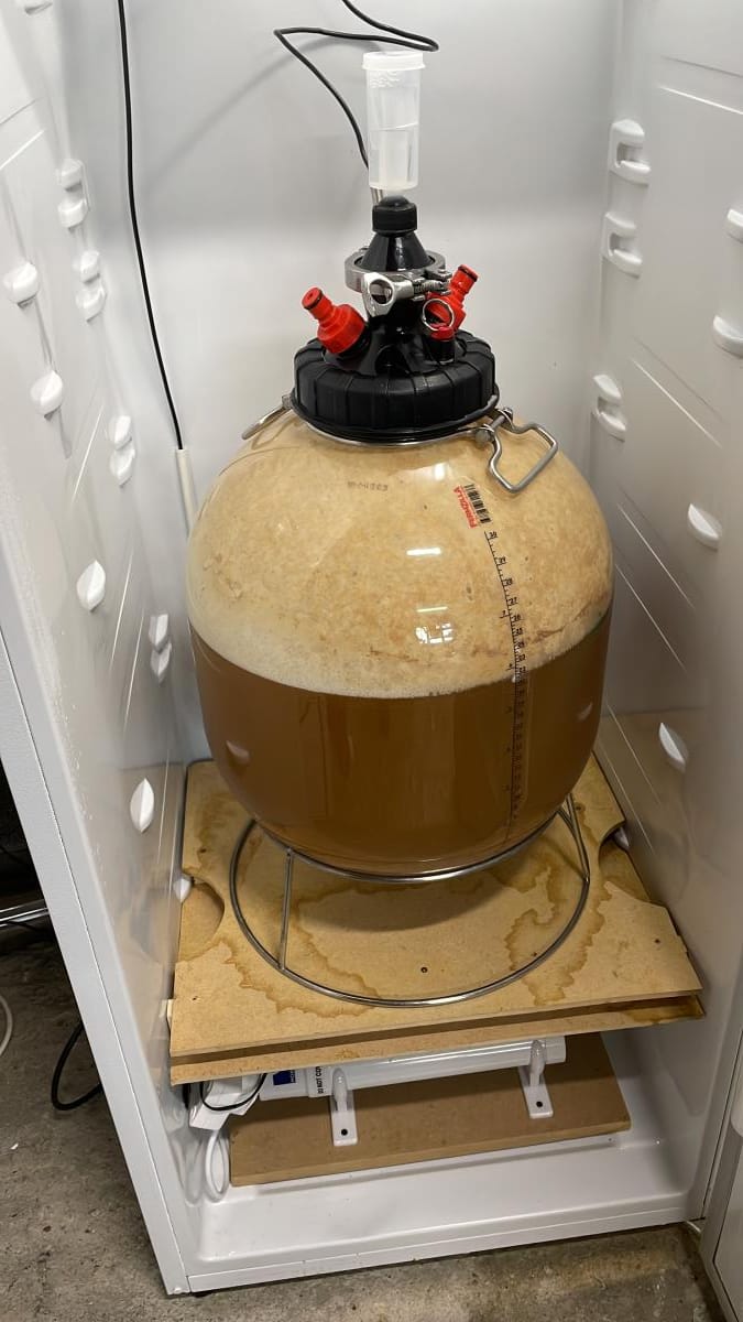
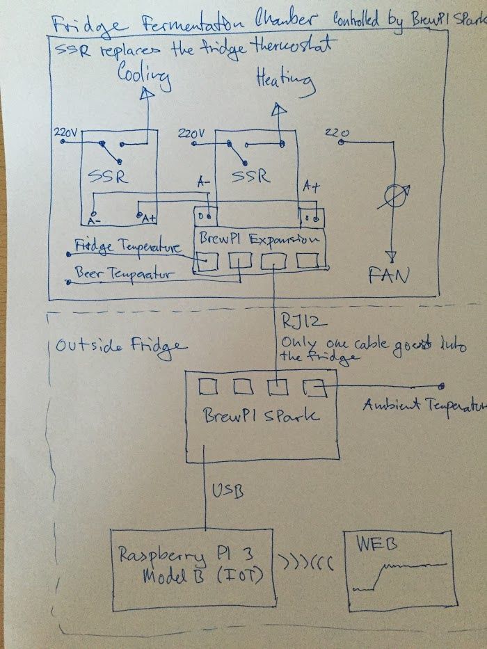
So now we've covered the basic architecture of the system lets get into the building the fridge which essentially looks like this.
First we hack the fridge thermostat so that the compressor circuit is bridged to be on 100% of the time.
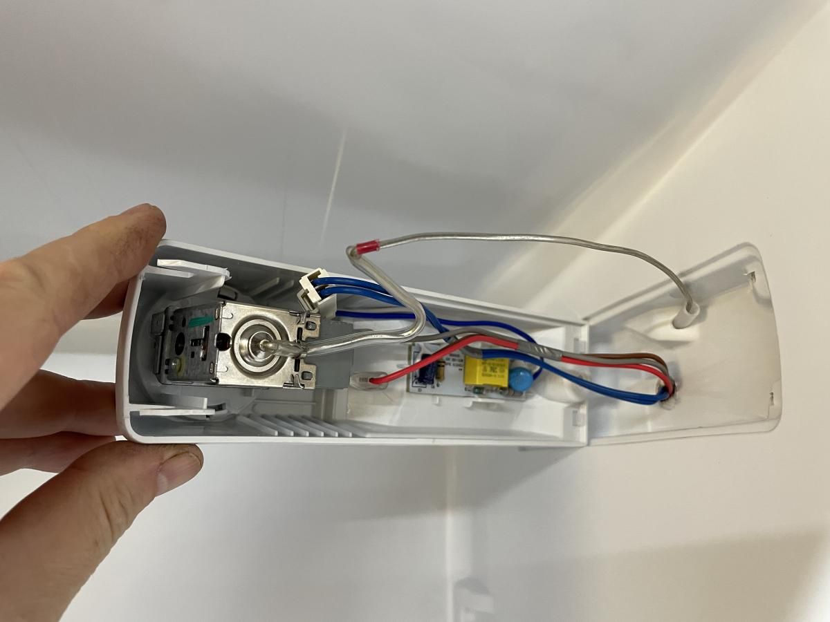
Then we have to find the feed to the thermostat and splice a Solid State Relay (SSR) into the circuit so that the Spark can now turn the cooling circuit on/off.
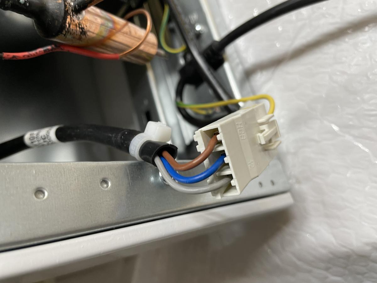
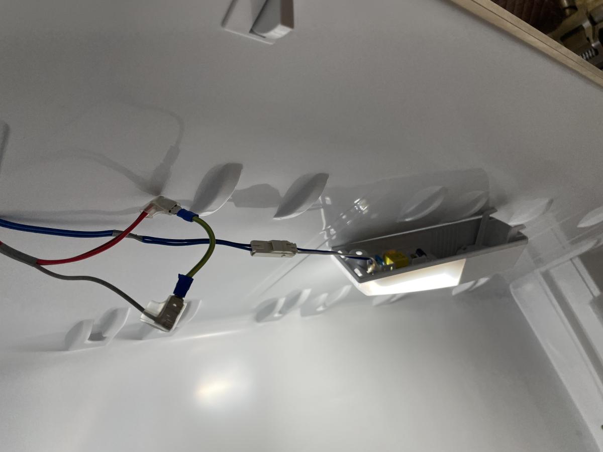
In the left shot directly above you can see the heat-shrinked joins tapping into the Neutral (blue) line to power the 60w tube heater and Live (brown) line to feed the 230v live side of the two SSRs. The black SSR switches the cooling circuit on/off and the sand coloured one powers the 60w heating tube and 120mm computer fan used to heat the fermentation chamber.
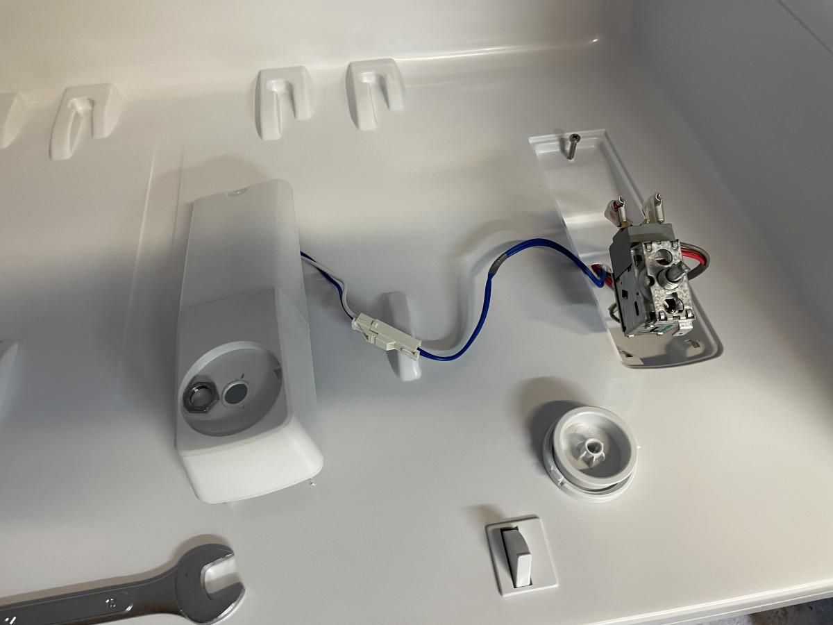
At this point the only live circuit in the fridge when it's plugged in and turned on is the door switch for the internal light. The bridged live circuit which runs though the thermostat housing now terminates with a crimped eyelet connector ready to be screwed to the 230v output side of the SSR.
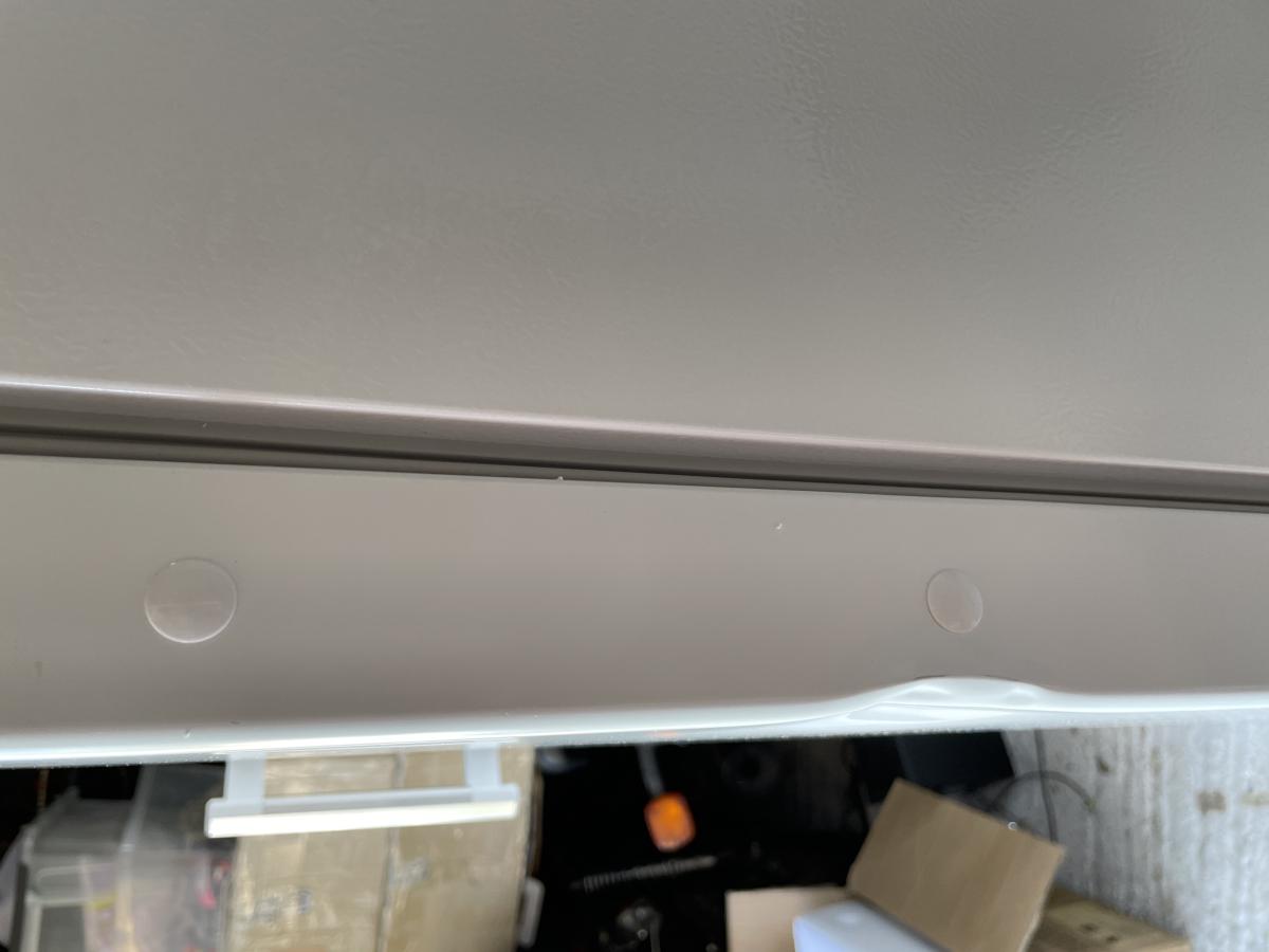
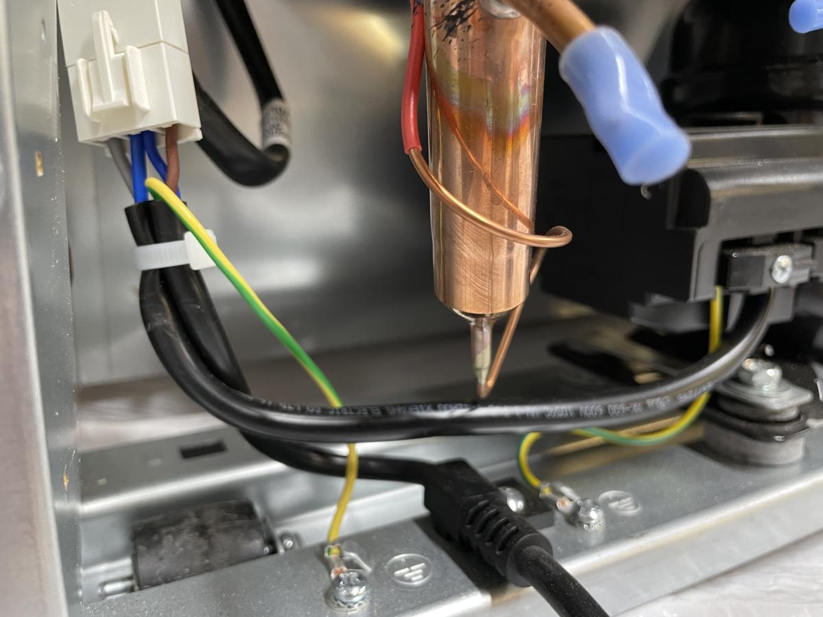
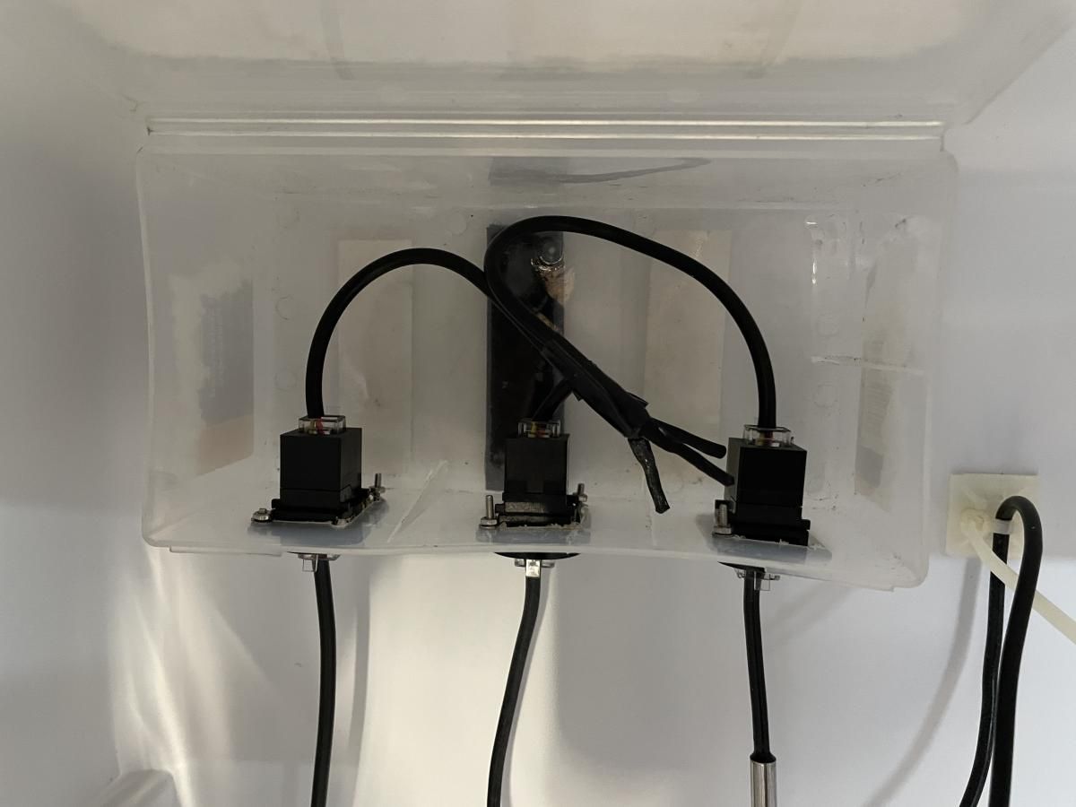
Inside the fridge, there's now a junction box made from an old plastic container which contains 3 x RJ11 sockets spliced together onto a single cable which runs back to the Spark. This pluggable box added after I had completed the original spliced build and allows me to unplug and replace the longer Beer Temp sensor, or the shorter Fridge Temp sensor and still run a single cable back to the SSR Expansion board through the very tight drainage hole in the bottom of the fridge.
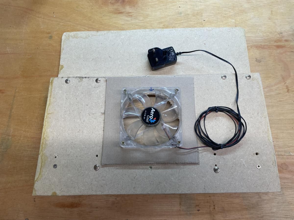
The Tube heater and PC fan are supplied power from a Dbl socket extension cord which is wired into the SSR and fridge neutral circuit as shown above. This ensures both the tube heater and fan run at the same time.
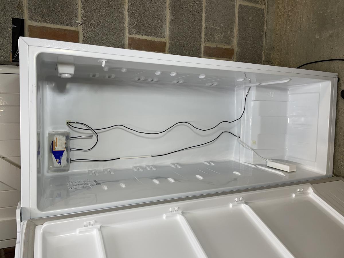
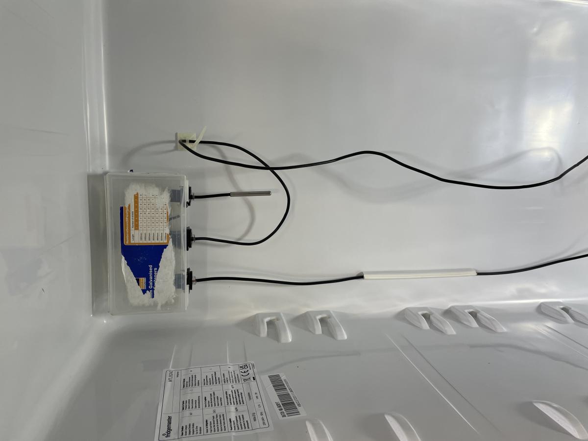
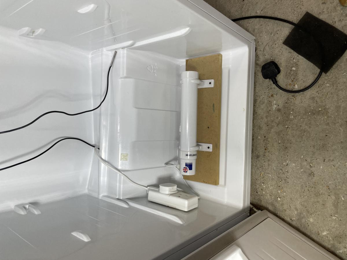

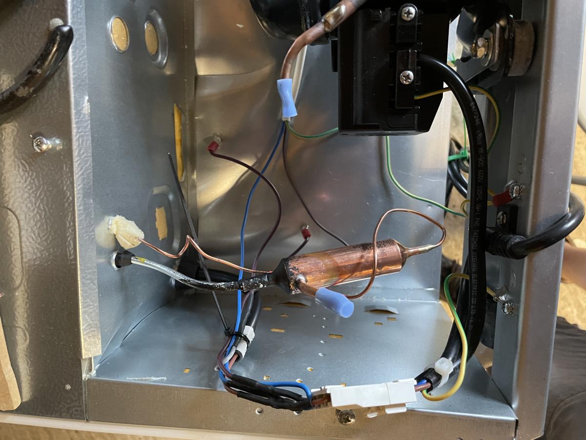
The inside - temp sensors, heating tube and distribution fan.
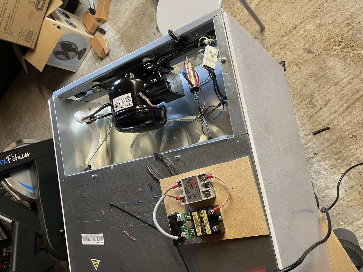
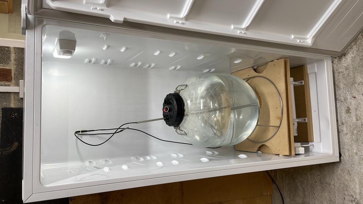
And here's the finished fermentation chamber ready to go as I originally built it, without the RJ11 distribution box. I worked out I needed this when the shrink wrap on a cheap Amazon sourced DS18B20 sensor that I was using in the Beer thermowell leaked and ruined the sensor and I needed to swap it out. Hard wiring it originally made that a challenge.
NB: The slightly more expensive DS18B20 sensors sourced from BrewPi are 100% waterproof, sealed with Epoxy.
Things to improve.
- Mount the SSRs in a box.
- Move the dbl socket outlet to the top of the fridge and run longer cables from the tube heater and PC fan
These are ok for Fridge Temp and Air Temp sensors, but I won't use them in thermowells that might fill with wort/water again. Note use of shrink wrap.